Hardware
The MLS800 is built around two surface mounted PCBs: a motherboard that holds the main unit and rear connectors, and a daughter board that contains elements the user interacts with during use.
Those two boards fit in a custom designed hot rolled steel enclosure with self-clinching fasteners and digital printing for a nice, professional-like finish.
The motherboard
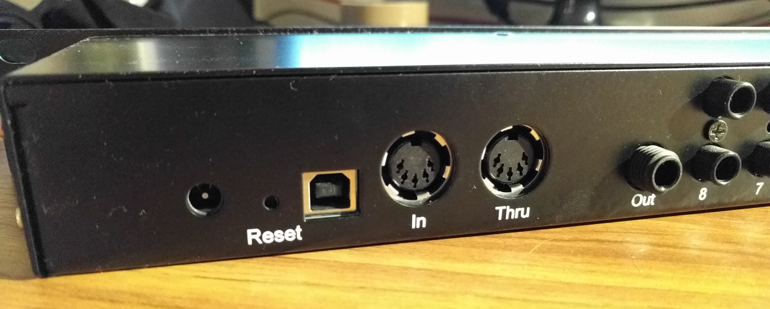
The MLS800 is based on the Arduino Micro design. As such, it is powered by an ATmega32U4. The ATmega32U4 does not need an additional IC to interface with a USB port and provides 2 hardware serial ports out of the box. The MIDI protocol being a serial communication protocol, this choice made perfect sense.
Connected to that processor are several ICs. A MCP23017 port expander drives two ULN2803ADW NPN arrays. Each pair of NPN transistor drive one V23079E1201B301 bistable relays. This design allows to keeps things simple on every level. PCB traces are kept parallel and changes sides as few times as possible, and port A of the MCP23017 is used to turn loops ON while port B turn them off. Bistable relays allows reducing power consumption, as power is only needed while changing their state. Finally, an 24LC256 EEPROM is used for preset storage.
The power is supplied by 2 LM340MP-5.0/NOPB each capable of delivering 1.5A@5VDC.
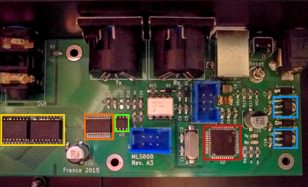
- ATmega32U4 main processor
- MCP23017 port expander
- 24LC256 256Kb EEPROM
- 2 ULN2803ADW NPN arrays
- 2 LM340 regulators
The input board
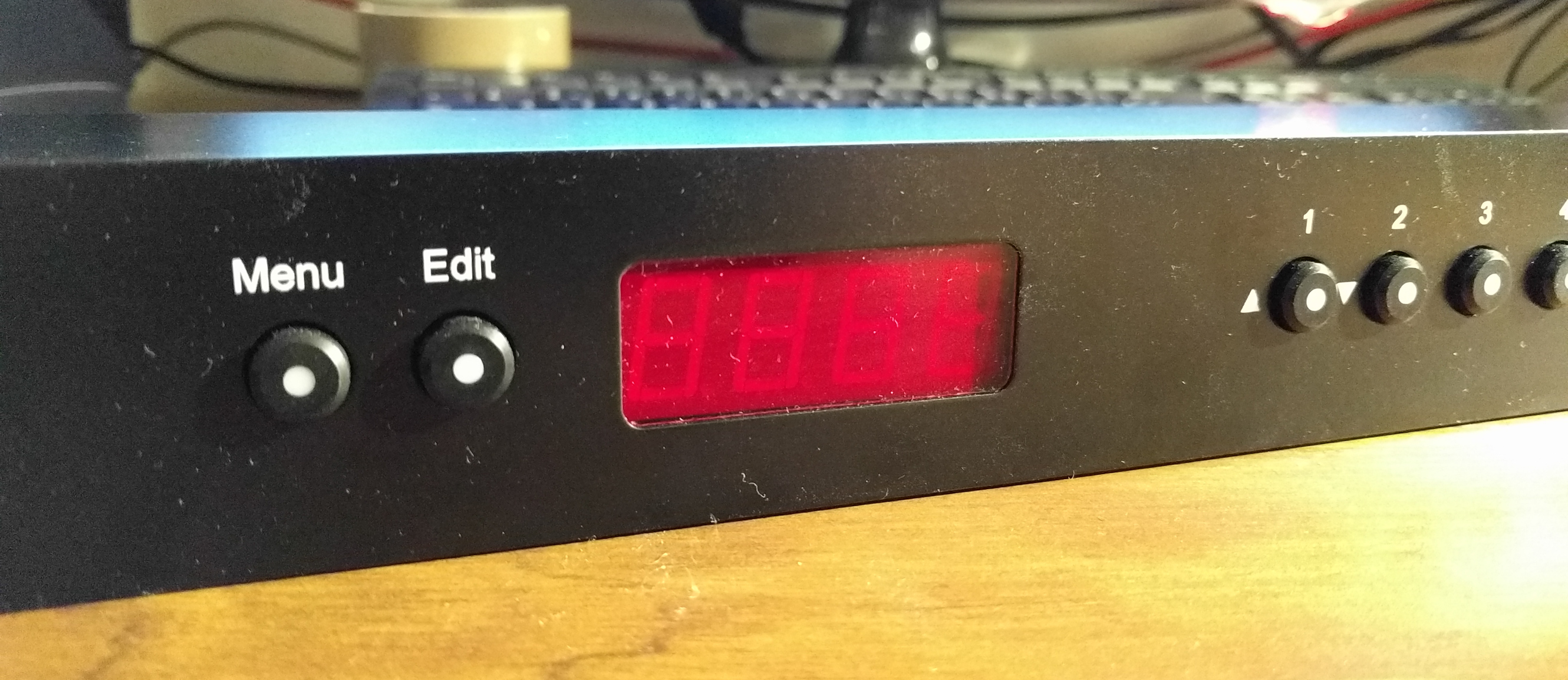
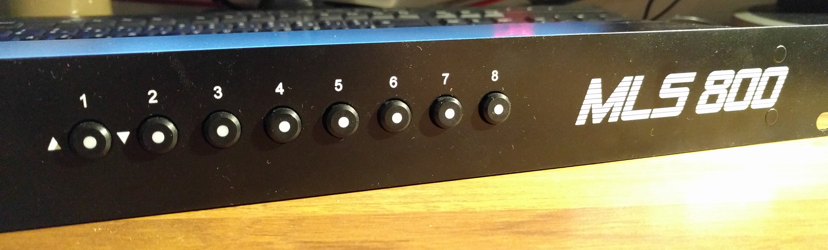
The input board is simply a daughter board that connects directly to the motherboard. It contains a LTC-5723HR 4 digits 7 segments display and 10 high quality illuminated Apem MEC switches switches (5GSH93582 combined with 1ES096 caps).
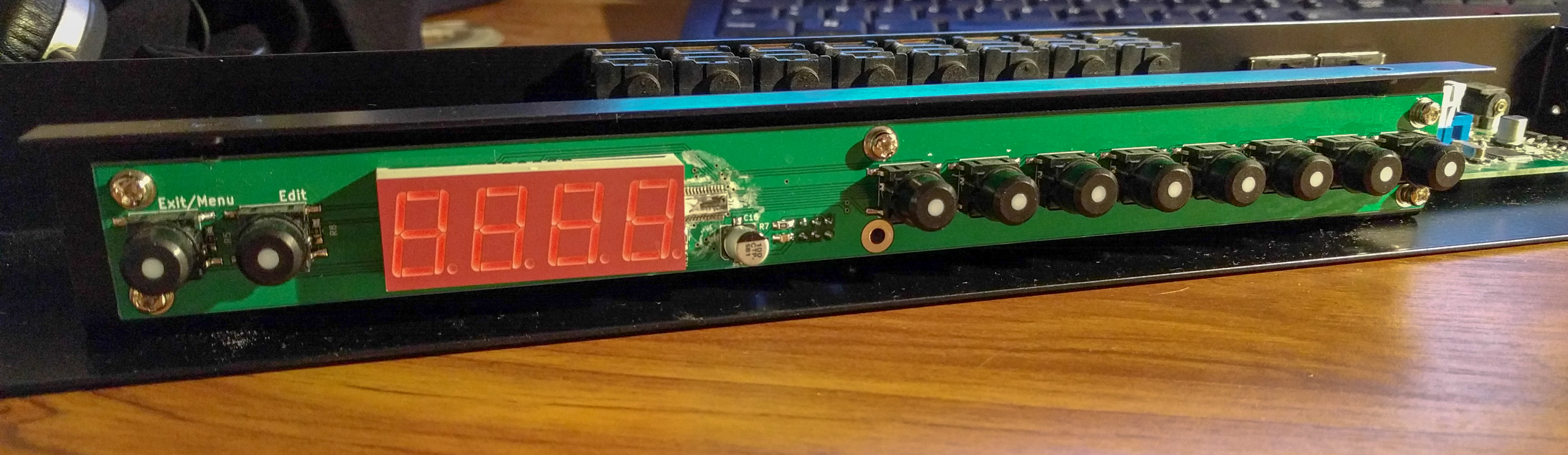
The display and 8 of the switches are controlled by an AS1115-BSST, while the two remaining switches are controlled directly by the main processor. The AS1115 being capable of driving up to eight 7 segments, a neat trick is to consider the 8 LEDs of the loop switches as a fifth digit. Saving ATmega32U4 pins, power, and reducing component count at the same time!
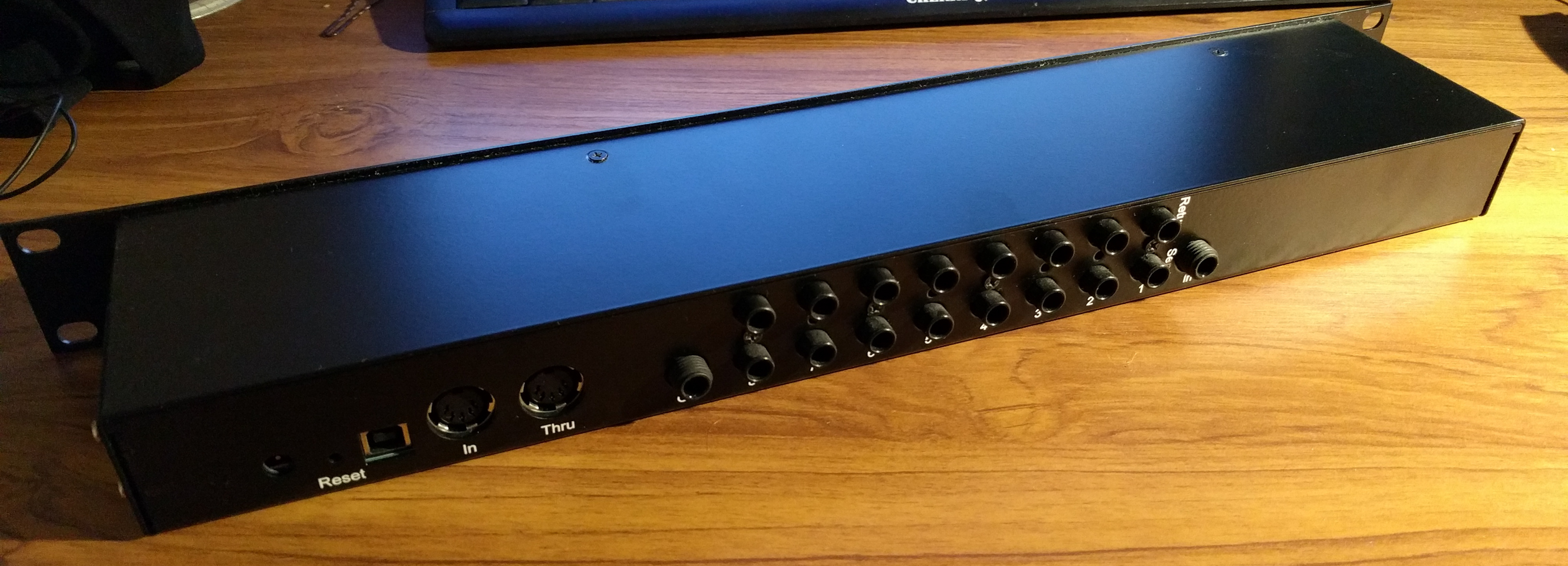
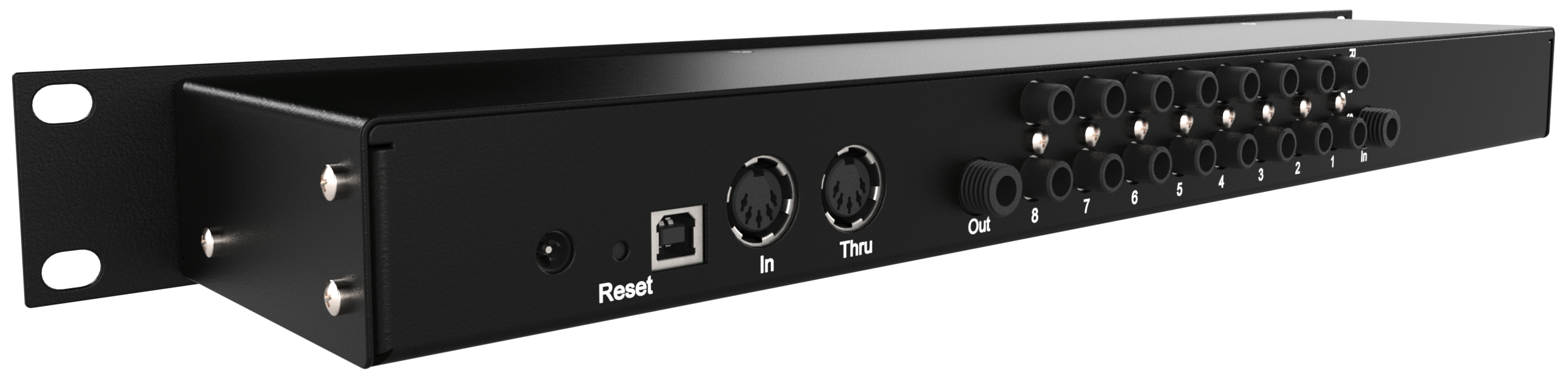
The enclosure
The enclosure is made out of 4 black painted and bent hot rolled steel sheets and assembled with self-clinching fasteners. It helps to keep the out surface smooth and gives the overall a professional-like finish. A laser cut acrylic bezel and the digitally printed front panel helps push that feeling even further.
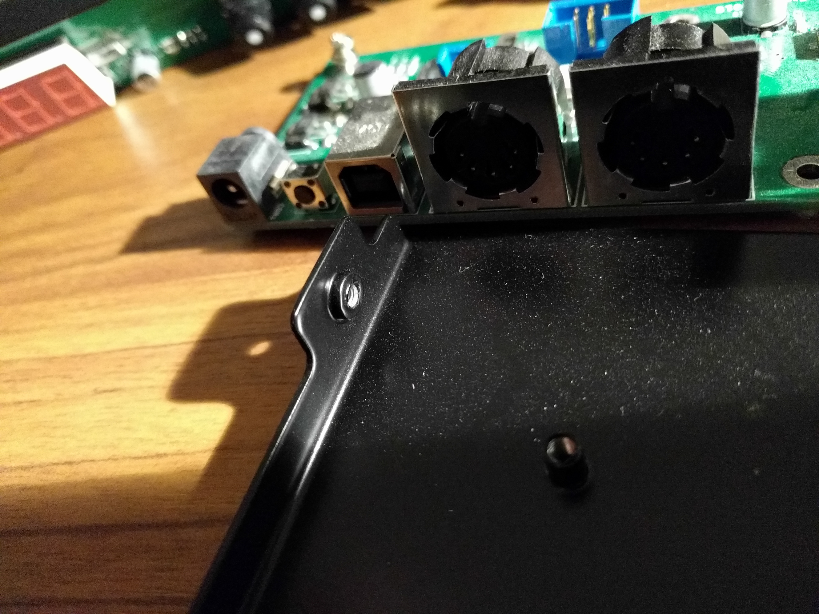
Another choice I’m really happy with is using NSJ8HC stacked jacks header. Even if they are expensive, they reduce the PCB length, and also provide a tightening screw which helps relieve the pressure against the motherboard when inserting jacks.
I’ve sent the case files over to a Canadian company, Protocase, and - oh boy - they’ve done an outstanding job building it! The good thing is they’re able to produce parts from start to finish, including printing them. The enclosure you see on the pictures is the one I’ve got straight out of the mail, including the screws!
When one passes by my gear and ask about it, he does not notice that one of the racks is entirely “home” made. I really highly recommend Protocase if you ever need this kind of service.